Thursday, November 29, 2012

Progress

I've decided on the style of amp to use. With one cell of power, a small voltage amp stage followed by a Sziklai pair emitter follower seems to provide enough power to headphones. The voltage stage, with pots on both the collector and emitter, gives a nice range of clean to dirty sounds. You can see the rest setup below.

The adjustment process is a little weird. The collector register has to be tuned to the emitter degeneration in order to provide the right offset for the current output stage. Along with the volume control at the input, that makes for three knobs. I've sketched out an intriguing layout and am testing it with some scrap pictured here.

Monday, October 29, 2012

Revelations

I spent understanding now how high-impedance inputs can have noise problems, and how to reduce those by isolation. That didn't have any impact. I also looked closely at what I was setting my gain to (near unity), and realized that my estimates on the pickup voltage levels were way too low. So I think I don't actually need nearly as much gain as I thought I did. I tested this by just running the pickup through the output stage, and seemed to get good results. I'll run it through the four-track tonight so I can listen more carefully.

While this makes the final amp substantially simpler, it also excises my solution to the tone problem. Perhaps I'll have to stick a conventional second-order filter in.

Thursday, October 4, 2012

v1.2

I tried series feedback on the v1.1 model, and started picking up BBC World News without any other improvement. So maybe those spice model freakouts were accurate.

I thought a little bit more about a long-tailed differential pair, and decided I could use one after all. I had originally rejected it because one needs a current source and/or mirror for it to have good amplification. But I have plenty of gain due to my multiple stages, so don't need the LTP to have much umph. In addition, because the LTP has a non-inverting output, I can use just two following stages and so not increase my overall transistor count at all.

It did seem more convenient to use a virtual earth to offset the input and feedback. The spice modeling looks really good. Hopefully it will work in practice too.
I see that I mention a volume control, but didn't draw it in. I figure to place it at location C, so that I can turn down the volume and still keep distortion. That doesn't seem to work, though. It does reduce the amplitude, but introduces its own unique kinds of distortion. So maybe an in-line resistor in the headphone would work better, but according to spice that distorts as well.


Monday, October 1, 2012

Noise

This is without any negative feedback. Something is going wrong with the shunt feedback I initially tried, so I took it out for this recording.

Tuesday, September 25, 2012

V1.1 Actualized

Still need to add jacks and a volume pot. The power and ground buses are on the back side of the breadboard. Still figuring out layout; breadboards are a pain and I can see the appeal of designing a PCB.

Thursday, September 20, 2012

V1.1

My original idea of a Sziklai pair for the output buffer was good. My abort for the first version was based on a faulty understanding of when a BJT goes into saturation. I like the pair output buffer a lot better.

There's also an interesting effect when the input to the pair goes over 1.4V: the first transistor goes into saturation and starts pulling a lot of base current. In my configuration, this would pull down the last gain resister and so function as negative feedback. I wonder if this softens the clipping at all?

(Note there should a Miller capacitor in the last gain stage too.)

Tuesday, September 18, 2012

V1

I felt that the paired output buffer mentioned in the previous post wasn't a good idea, although this one, which seems more sensible, isn't achieving quite the same game; final output into 20Ω is barely a milliwatt. We'll see how it works... Happily enough, the performance didn't change between arbitrary resister values, and values that I have laying around the workbench. I think that's a good sign for my design.

Friday, September 14, 2012

Turning Up the Noise

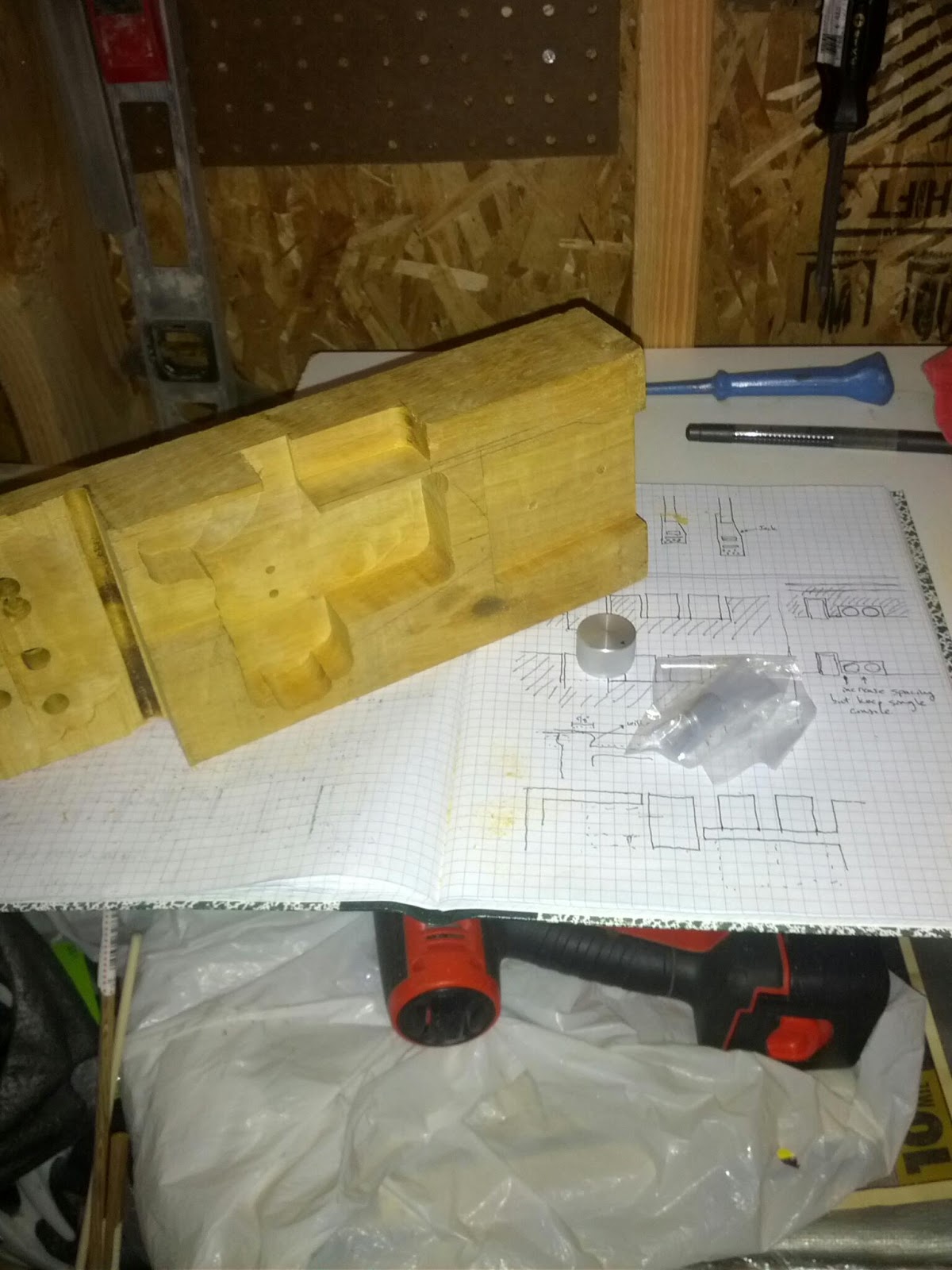
I moved quickly through the sawdust portion of this blog. Maybe I will return to it at some point. So far I don't think I've done anything that isn't obvious to someone who's spent more than 20 minutes with a router. I did learn a lesson after destroying one pickguard template (have shallow and deep pattern bits), and there was the aforementioned problem with the bridge placement. Otherwise the build went smoothly.

There's a couple more things to figure out. I've sewn the headphones into the strap, and am still experimenting with their placement. The balance is a little off; I've adjusted one of the strap buttons already to keep the body from tilting down, and will be moving the neck button up to the top of the guitar to allow it to hang better centered.

All of that will wait until I get the first version of the headphone amp: the noise portion of this blog.

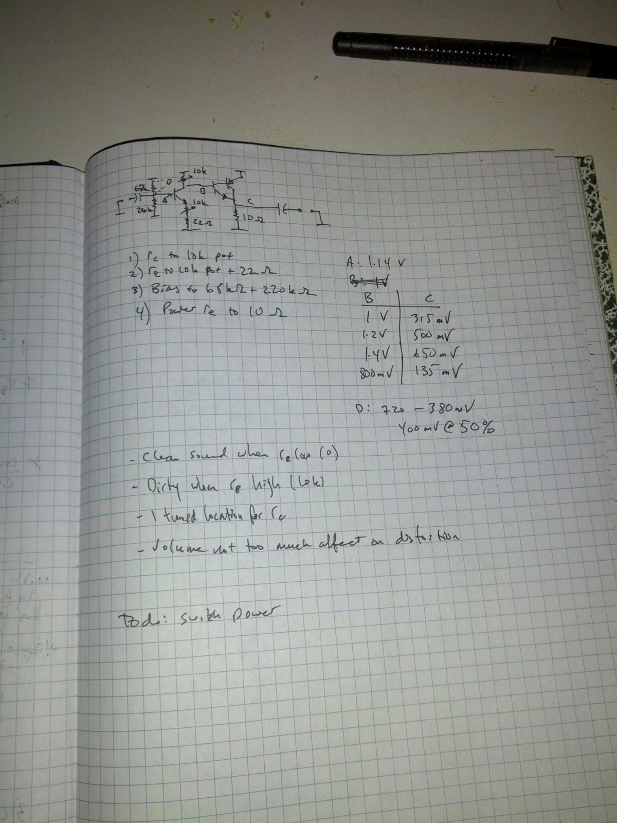
As mentioned, I want to try to make a one-cell amp, mostly as an excuse to use up the bag of transistors I have in the garage. The basic design is this.
The fundamental gain component is a buffer (emitter-follower) and a degenerated common emitter with degeneration bypass and a Miller feedback capacitor. This was the result of a lot of simulation and design for something that has microamps of quiescent current, robust with respect to component values, and has high input impedance. The buffers seem necessary to chain these stages together, and a single gain transistor isn't sufficient given my low voltages. These don't chain together perfectly, even with alternating between npn and pnp transistors, as the best input offset is less than the output offset, but a spice simulation of putting three together ends up working good enough. To drive a 20Ω output I needed a paired buffer pulling 20mA quiescent. That's enough to take a 5mV peak input to 200mV. I'm sure I'll need to tweak this after soldering up the first version. Note that 2 stages would probably provide enough gain, but I want three so I can have global feedback.

The idea of the Miller feedback is to get a second or third order high frequency filter in order to cope with the overly bright tone. I've had a chance to travel with this over the last few weeks (as pictured), and have tended to zero out the tone dial on the amPlug amplifier I'm using. It's tolerable, but somehow simultaneously ringy and muddy.

As you can see in the picture above, I did some math to figure out what the gain would be as a function of the capacitors, ignoring the buffers. Naively plotting this along with some simple feedback gives the following frequency response. This matches up with the spice simulation (which includes the final output pair and a 20Ω load), with one exception.
I think there's something weird with the spice simulation, because it's reporting 70dB of gain even though looking at the waveform in a transient plot shows something like 30dB of gain. We see with three 4nF capacitors we roll off at 1 kHz nearly at a 3rd order rate (18dB/octave). Dropping the capacitors to 500pF moves the shoulder to 6 or 8 kHz which may be more reasonable. I'll have to let my ear decide. I don't know what harmonics are necessary for a string to sound good.
There are some oddities. In the theoretical plot, there is ripple as the gain is reduced.
This can be much reduced by spreading out the capacitors, for example using 800, 500 and 100 pF capacitors rather than identically 500 pF.
So far so good. However, when looking at the transient waveform simulation, weird stuff is happening. With all 500 pF caps and varying the (shunt) global feedback from 10kΩ to 5kΩ to 1kΩ we have the following at 500 Hz.
At 10kΩ we are clipped. As we decrease the gain we get some weirdness. I originally thought it was due to the phase shift from the capacitors. My theory tells me the phase shift is negligible at this frequency, but my theory could be wrong.
Plotting at 100 Hz, which should be well away from any shift, is closer to what I'd expect, but there are artifacts that make me distrust what spice is doing.
In addition, you'll note that I start the transient analysis well away from zero. This is to eliminate what looks like a capacitor charging, even though that should be dealt with by the operating point calculation that I thought spice did. Hmmm.

At any rate, the ripple never shows up in the frequency plot. But then, that plot is also always pegged at 75dB of gain regardless what size feedback resister I use. I think I'm missing something fundamental about how spice .AC analyses work.

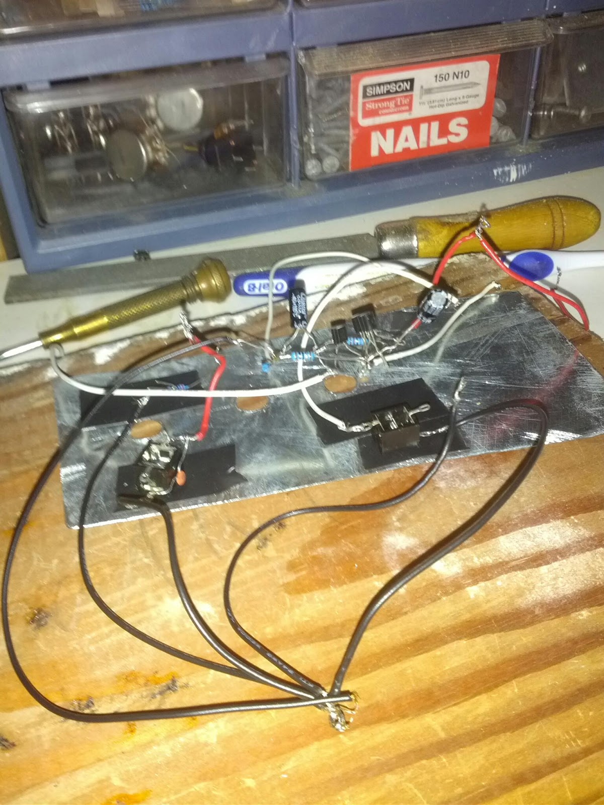
In spite of all this, I feel like there's enough agreement between my theory and the spice simulation that I should solder this up and see what it sounds like. It's a bigger amplifier than I was hoping for (8 transistors), but it has a lot of flexibility in frequency shaping that I hope will make it fun to play with.

I'm even less skilled at soldering than I am at woodworking, if such a thing is possible, so this next stage should be interesting to watch.

Saturday, September 8, 2012

Utility

It wouldn't be much of a travel guitar if I didn't travel with it.

Friday, August 24, 2012

The next step

I've done a pretty good job on the sawdust part. I think I'm going to have to cut away the body under the neck to make the higher frets easier to reach. Other than that I'm happy with the design.

The next step is to get rid of that ugly headphone amp sticking out on top. This is the noise part of the blog. The idea will be to build a custom headphone amp into the body. I have some ideas on how to do this using only one cell, which would be slick.


I know it would be easier to open up the Vox headphone amp and just stuff that in the body. Building a headphone amp from an op-amp rather than transistors is not as obvious, as most op-amps need 9v supply, and I'd prefer to use AA batteries as that's what the rest of my electronics use (including the 4 track, which is a very plausible thing to bring along with me on travels).

The guitar's tone is harsh, probably due to the very short reach of the strings past the bridge as well as the general lack of resonance in the body. The tone is turned way down, but still sounds muddy. So another goal of the headphone transistor is to be able to fine-tune the frequency response. At the very least, add enough distortion so that the poor tone isn't noticeable.

Back from the shop


I lowered the neck down, re-drilled the bridge, painted the pickup ring, and was a lot more careful about sanding before painting. I also moved the right-hand strap button to the end of the tuner extension. In its original location under the bridge, it tended to flip the guitar away from me, making it awkward to play. Moving over to the location shown here and passing the strap over the tuners makes the guitar flip up slightly instead.

I also did a little bit of sewing in the strap so I could route the headphones through it and reduce the tangle of wires.

Friday, August 3, 2012

v1: There's a lame paint job

Also, the neck is too high (and/or too much angle), the pickup ring needs to be painted and the bridge posts aren't quite right. They're a sixteenth of an inch too narrow, and I measured them from the middle of the bridge, and not the end closer to the neck. Had I thought about it I would have realized that the high-E string is closest to an ideal string and what the bridge and neck should be positioned to, with the large strings needing uniformly more intonation backwards.

An evening with a dowel, drill press, rasp and sandpaper will fix that nicely.

Thursday, June 21, 2012

Neck: Mangled


I countersunk the bottom so that the string balls wouldn't project as much. I got half the ferrules pressed in before Brian reminded me that I still needed to refinish the neck.

Note that the outer holes had to be angled because of the bevel on the bottom of the headstock. That's part of the reason why they don't line up very well and generally look bad on the bottom side (the other part being that I'm just not very good at this).

Monday, June 4, 2012

Notes

Notes on what I've done. It's convenient that the ruling in this notebook is exactly the same as guitar string spacing. The lower picture shows the dimensions for the tuner cut-out.

Marking the headstock

The string ferrules will be mounted on top, you can see the dots faintly following the arc of the cut. I'll probably countersink the back a little bit to seat the balls.

Wednesday, May 23, 2012

Movingui wood. Yellow with a bit of sparkle, dense, and the only piece thicker than an inch in the scrap wood bin.